This PLECS demo model shows a Lithium-ion (Li-ion), battery-powered, series-parallel hybrid vehicle system. The simulation shows the startup for an electrically and mechanically coupled hybrid system.
Power Circuit

Battery Modeling
The Li-ion battery is based on a resistor-only electrical model. This model enables users to take information from the battery datasheet to represent the current and voltage characteristics of a Li-ion battery pack as it is charged and discharged. Application notes on Li-ion battery modeling in PLECS can be found here.
Drive Systems
The series-parallel hybrid consists of two permanent-magnet synchronous machines (MG1 and MG2), inverters and associated controls. The DC-side of the inverters of both MG1 and MG2 are connected the DC-bus. MG2 is primarily used as a motor to aid the engine during acceleration. MG1 is used both as a motor and a generator. Both MG1 and MG2 system controllers consist of an outer speed loop and an inner current loop to regulate the rotor speed to a desired speed. The outer speed loop produces the torque setpoint for each machine. These torque set points are converted into dq-current set points. A digital synchronous frame regulator is used to regulate the current in each MG system.
Mechanical System
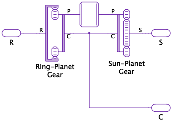
MG1 and MG2 are mechanically coupled to the engine via a planetary gear set (PGS). The PGS module has three mechanical ports to connect it to the sun, ring, and carrier gears. The PLECS PGS module internally consists of a ring-planet gear and sun-planet gear implementation. This allows users to introduce non-idealities into the planet gear to observe the effects on the overall system.
The ring gear is connected to both the rotor shaft of MG2 and the wheel. The engine is connected to the carrier shaft and MG1 is connected to the sun gear. This configuration allows the engine and MG2 to provide the driving torque for the wheel, while MG1 is controlled to maintain the engine speed at the desired level.
Try it
This model is available in the PLECS Demo Model library provided in both versions of PLECS.