This PLECS demo model shows an inverter-fed, 8-pole, non-linear permanent-magnet synchronous machine (PMSM) configured with FEA data. The FEA data was generated for a Toyota Prius motor model in Infolytica's MotorSolve platform.
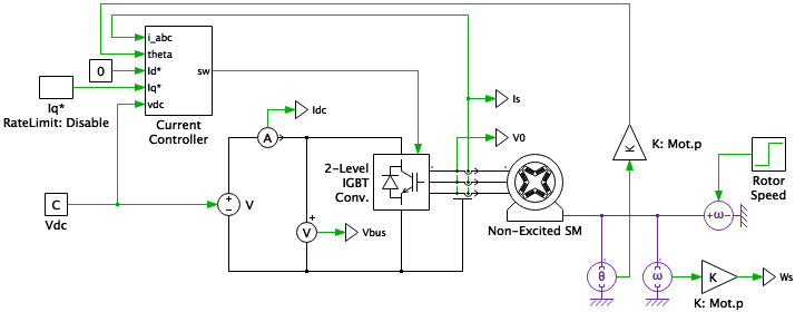
Electrical Circuit
The "Non-Excited Synchronous Machine" component enables the use of lookup tables to configure the machine. These lookup tables can be obtained from FEA tools such as Infolytica's MotorSolve platform. The lookup table approach allows the incorporation of machine saturation and cross-saturation effects.
The machine is operated at constant speed to study the performance of the current controller. This is achieved by connecting a PLECS Rotational Speed source to the mechanical terminal of a PLECS machine model. The machine inertia must be set to 0 Nms2 to operate the machine with a speed source. The inverter circuit is modeled as an ideal three-legged bridge with a stiff 200 VDC supply.
Controls
A synchronous frame regulator is used for the closed-loop control of the currents. The machine mechanical speed, mechanical angle, and stator currents are measured. The mechanical speed and angle are scaled by the number of pole-pairs to determine the electrical speed and angle, respectively.

Direct and quadrature current setpoints are provided to a current regulator. This regulator is decoupled based on motor speed and also includes state-limiting and anti-windup mechanisms. Typically PI controllers are used for current regulation in the d- and q-axes. The gains of the controllers and the system decoupling are based on the motor parameters: motor speed, motor incremental inductance (Ld and Lq), and stator resistance. For a machine driven into saturation the Ld and Lq values change. In this demonstration, the machine inductance in the saturation region is used for the controller design.
The three stator phase currents are being measured for closed-loop control. These are then transformed to DQ values inside the regulator and are compared to their setpoints. Space vector pulse-width modulation (SVPWM) is used to generate the output voltage of the inverter.
In this simulation all the torque is produced by the magnetizing q-axis current and reluctance torque is maintained at 0 Nm. As the machine is driven into saturation the incremental inductance values change. One solution is to use lookup tables for the decoupling parameter and PI gains to optimize machine performance. An alternative approach that is included in this model is to limit the rate of change in the current setpoint, which will decrease the magnitude of the q-axis error. Thus, the effects of a mismatch in the decoupling parameter and the changing machine incremental inductances are reduced. This causes the d-axis current deviation due to change in the q-axis current setpoint to decrease.
Try it
This model is available in the PLECS Demo Model library provided in both versions of PLECS.