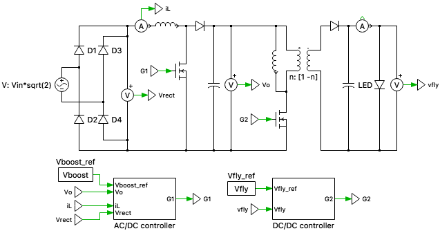
This PLECS demo model shows the design of a two-stage LED driver circuit consisting of a boost-PFC for AC/DC conversion followed by a flyback converter for DC/DC conversion.
For LED drivers in general lighting applications, the induced line current harmonics must comply with IEEE Std 519-2014. Generally, it is difficult to meet these requirements without power factor correction (PFC) techniques. In the two-stage LED driver circuit designed in this model, the first stage provides a near unity power factor and a low total harmonic distortion (THD), while the second DC/DC stage is used to provide a tight regulation of the output. The Boost PFC converter attempts to draw a current that is always in phase with and at the same fundamental frequency as the line voltage, while maintaining a constant DC bus voltage on its output.
The LED load is represented by a non-linear V-I curve obtained from the forward current characteristic curve (forward voltage vs forward current). For the LEDs considered in this model, the typical forward voltage is 3.2 V and typical forward current is 350 mA; ten of these LEDs are connected in series to form a "light engine".
Control
The two-stage LED driver requires two independently controlled power switches and two control circuits for AC/DC and DC/DC conversion.
The AC/DC controller comprises of an inner current loop that operates faster than the outer voltage loop. The voltage compensator regulates the DC output voltage, by comparing the sensed DC output signal against a reference. The output of the voltage loop is proportional to the amount of power transferred by the PFC converter. This output is then multiplied by the rectified input voltage and the inverse of the square of the RMS input voltage, implementing fast feed-forward control. This modulates the voltage controller output such that the PFC input current and the PFC input voltage have the same phase. The resulting product is compared against the sensed PFC rectified input current. This error is the input to the current loop. The current controller generates the PFC duty ratio command such that the PFC input current tracks the reference current.
The DC/DC controller is used for voltage regulation. The error signal obtained by comparing the measured output voltage (DC) against a voltage setpoint is given to the controller for voltage compensation. The resulting value is provided to a modulator for PWM generation.
The controllers in both these cases have been tuned analytically using the K-factor method, based on the respective plant transfer functions of the converters. The K-factor method is a loop shaping technique, where a controller can be designed accurately for a specified phase margin and crossover frequency.
Try it
This model is available in the PLECS Demo Model library provided in both versions of PLECS.