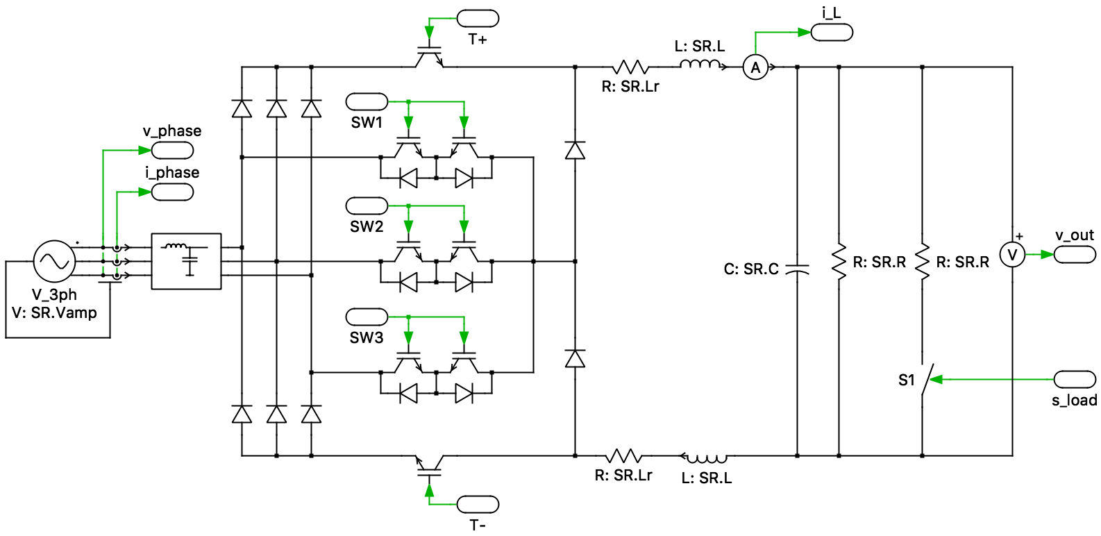
This PLECS demo model shows a Swiss Rectifier (SR) with an output power of 5 kW.
Control
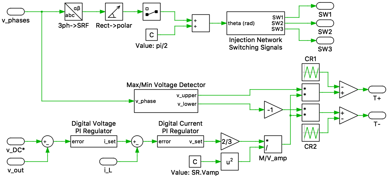
The controls of the SR are divided into two main parts: injection-network control and fast-switching controls.
The grid-side three-phase voltages are measured and the instantaneous phase angle is determined. The phase angle information is fed into a look-up table, which is used to generate the switching signal for the injection network switches.
The fast switches of the SR are controlled using a cascaded digital controller with an inner current loop and an outer voltage loop. The output voltage of the SR is measured and compared with a reference. The voltage error is fed into a digital voltage PI regulator and generates a current setpoint. The inductor current is measured and compared with the current setpoint. The error is fed into a digital current PI regulator, which generates a voltage setpoint. This voltage setpoint is translated into a modulation index (M) given by:
M = 2⁄3(Vset⁄Vamp),
where Vset is the voltage setpoint generated by the current regulator and Vamp is the peak value of the three-phase grid voltage.
The three-phase voltage measurements are also used to determine the instantaneous maximum and minimum phase voltages (Vupper and Vlower, respectively). These are then used, along with the modulation index, to determine the duty cycle of the fast switches. The duty cycles, α+ and α−, for T+ and T−, respectively, are given by:
α+ = M(Vupper⁄Vamp)
α− = − M(Vlower⁄Vamp)
Try it
This model is available in the PLECS Demo Model library provided in both versions of PLECS.