This PLECS demo model examines a current-controlled permanent magnet machine under several drive fault mitigation strategies. The system includes an inverter with field-oriented control (FOC) that supplies the machine operating at a constant speed. Fault conditions such as loss of auxiliary power supply or microprocessor trip can result in loss of power to the inverter. Usually under such faults, the power stage is disabled. However, when operating in flux-weakening mode, a fault mitigation strategy may be required as the rectified back-emf may be larger than the DC-link voltage. In this simulation, failure mitigation strategies by closing all the lower inverter switches or opening the battery pack contactor are investigated.
Power circuit
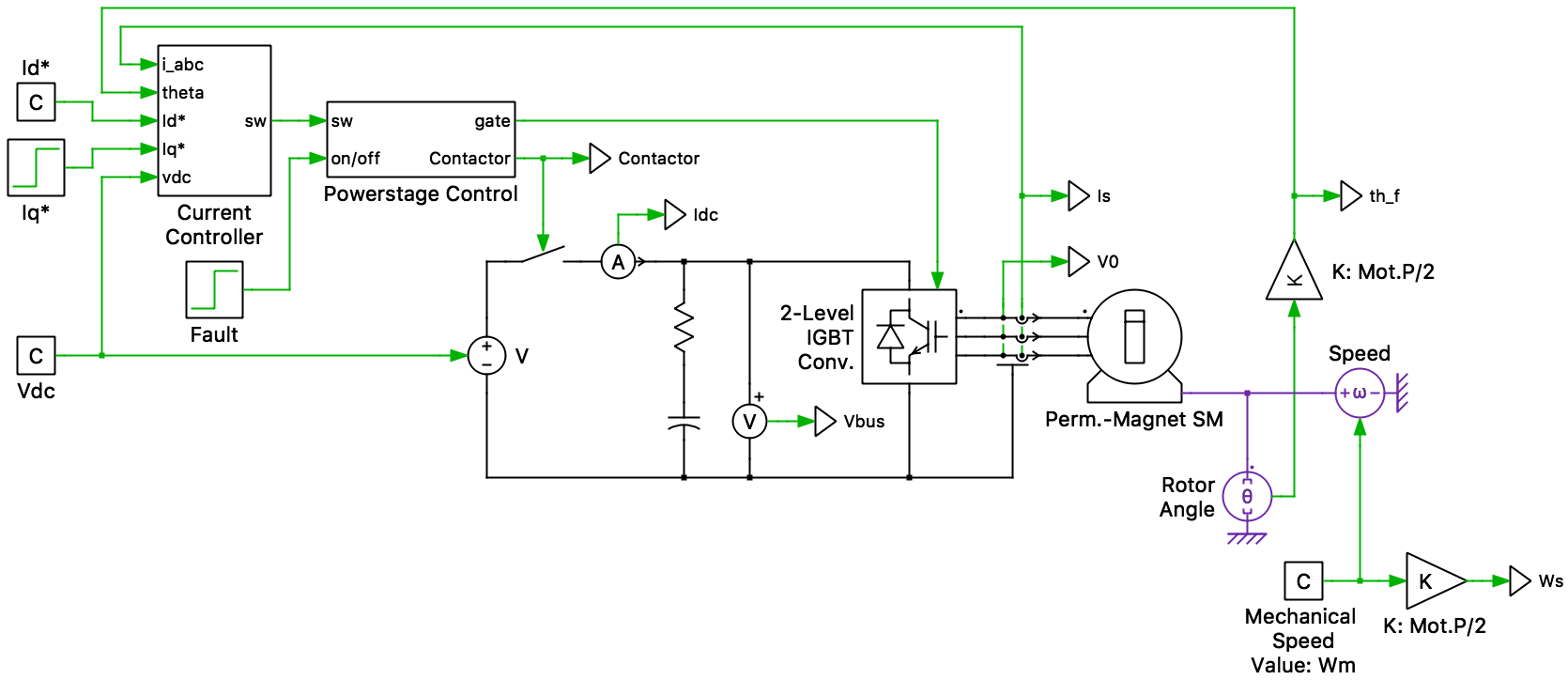
The circuit includes a simplified battery modeled as an ideal DC voltage source that feeds a 3-phase inverter and permanent magnet-assisted synchronous reluctance machine, i.e., a PM machine with high saliency. The machine model is configured to use the voltage behind reactance (VBR) implementation, as this will allow for the simulation of fault conditions, during which the phase voltages are no longer defined by the inverter. A contactor between the battery and DC bus is also included and is represented by an ideal switch.
Control
Direct and quadrature current setpoints are provided to a current regulator. This regulator is decoupled based on motor speed and also includes state-limiting and anti-windup mechanisms. The three stator phase currents are measured for closed-loop control and are transformed to DQ values inside the regulator and compared to their setpoints. Space vector pulse-width modulation (SVPWM) is used to generate the output voltage of the inverter and a configurable dead time is also included to prevent shorting of the DC bus.
The direct current setpoint (Id*) is held constant at -200 A to operate the machine in flux weakening mode. The torque-producing quadrature current setpoint (Iq*) steps up in value from 0 A to 100 A.
Under fault conditions where the rectified back-emf is smaller than the DC-link voltage, disabling the power stage may be sufficient. However, when operating in flux-weakening mode the rectified back-emf is larger than the DC-link voltage. Simply disabling the power stage would result in an uncontrolled current flow from the machine into the battery, resulting in an uncontrolled braking torque on the load. A fault mitigation strategy for this situation will be required to prevent this unregulated power flow to the battery.
The power-stage control subsystem can be configured to mitigate this fault condition with two different strategies:
One fault mitigation strategy is to open the battery contactor when a power failure is detected. Opening the battery contactor would prevent the current generated by the back-emf to flow back into the battery pack. This strategy would result in charging up the DC-link capacitor until the bus voltage is equal to the rectified back-emf of the PM machine. This would damage the semiconductor devices, the bus capacitors, and all other systems connected to the bus unless these components are oversized.
Another fault mitigation strategy is to short the machine phases by closing all the lower switches of the inverter. The back-emf of the PM would result in large motor currents that would produce a decaying oscillatory torque. One concern for such a strategy is that shorting the motor phases may lead to large currents thus requiring oversizing of the semiconductor devices. In this strategy keeping the battery contactor open or close has no effect as the machine currents are not flowing back into the DC-link.
Simulation
This model can be first explored to see what happens when a fault is introduced into the system under flux weakening operation. When the fault is detected the power stage is simply turned off by opening all the inverter switches, resulting in a current flow from the machine into the battery and a braking torque on the load.
Configuring the Powerstage Control subsystem to open the battery contactor when a fault is detected will show that the DC-link voltage suddenly increases as the motor currents flow into the DC-link capacitor. This occurs until the DC-link voltage is equal to the rectified back-emf of the machine.
As a second fault mitigation strategy, configuring the Powerstage Control subsystem to close all the lower switches of the inverter shorts the motor phases together. This results in large motor currents that produce a decaying oscillatory torque.
Try it
This model is available in the PLECS Demo Model library provided in both versions of PLECS.