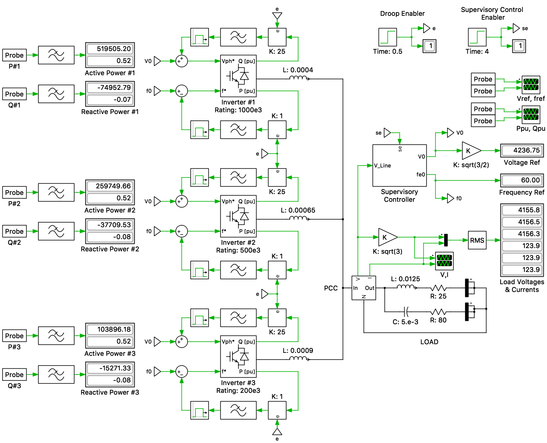
This PLECS demo model illustrates a microgrid with three active generators (solar, wind, etc.) of different VA ratings (1 MVA, 500 kVA, 200 kVA). A supervisory controller at the Point of Common Coupling (PCC) ensures that the frequency and voltage are kept at their rated values. Load sharing among the multiple generator units is provided by the local droop control. This demo model was developed by Dr. Luis Garces.
Microgrid Concept
A “Microgrid” is a system approach to view generation and associated loads as a subsystem. This approach allows for local control of distributed generation, thereby reducing or eliminating the need for a central dispatch. During disturbances, the generation and corresponding loads can separate from the distribution system to isolate the microgrid’s load from the disturbance without harming the transmission grid’s integrity.
High system reliability and generation placement flexibility can be achieved by a peer-to-peer concept, ensuring no specific component is critical for the microgrid operation, and a plug-and-play model, implying a unit can be placed at any point on the electrical system without needing to re-engineer the controls, for each microgrid component. This ability to “island” generation and loads has the potential to provide higher local reliability than that provided by the power system as a whole.
Microgrid Control
Microgrids are managed through both local and centralized supervisory controls. The system frequency and voltage references are dynamically determined by the supervisory controller, such that real power and reactive power sharing among multiple power generation units is provided by the local droop control.
The inverters themselves set their own instantaneous active and reactive power using active power/frequency (P/f) and reactive power/voltage (Q/V) droops. When in islanded mode, a microgrid is responsible for both voltage and power control.
Droop Control
In the transmission system, synchronous generators are equipped with P/f droop control to regulate their speed. When the output active power is greater than the input mechanical power, the generator slows down because energy is being extracted from its rotating inertia. This causes the frequency to decrease, resulting in reduction of terminal voltage, phase angle and AC power. However, frequency is a global paremeter, i.e., equal in the entire system and is directly linked to the speed of the generators. Therefore, each generator unit measures and "droops" its speed to reduce its input mechanical power. This results in accurate power sharing among different generators.
The P/f droop control method for a standalone microgrid is based on mimicking the operation of a synchronous generator. Since converter-based microgrids generally lack inertia, the P/f droop method in microgrids is based on transmission line characteristics. In inductive networks, active power (P) and phase angle (δ), and reactive power (Q) and voltage amplitude (E) are related by the power flow equations below. For the control, frequency is used instead of phase angle.

The above equations approximately represent a source E1 with a low phase angle δ to voltage E2 with phase angle 0 through an inductive line impledance jX.
In the conventional P/f droop control method, generator active power, P, is drooped proportional to the measured frequency, f. However, since frequency measurement in converter-based microgrids is not straightforward and active power measurement is easier, f is drooped as a function of P. At the same time, the amplitude of the voltage, V, is drooped with the measured reactive power, Q.
The P/f and Q/V droops for a given generator unit i are below:


where ω is angular pulsation (ω = 2πf), Kf and KQ,v are the droop constants.
The droops are coordinated to ensure each parallel inverter unit supplies active and reactive power in proportion to its rating while sharing the load. An advantage of the droop method is its simplicity, because no extra interconnections among the inverters are required. Therefore, high modularity, flexibility (i.e., plug and play integration) and good reliability can be achieved.
In the current demo, the individual inverter units are managed using open-loop droop and supervisory controls. Therefore, the individual frequency and voltage of the units are not dynamically regulated. The supervisory control changes the open loop reference (very slowly) to guarantee that the frequency and voltage at the PPC are maintained at 60 Hz and 4160 V, respectively.
Simulation
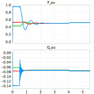
The model starts with both the supervisory controller and droop controller disabled. The per-unit values of P and Q are quite mismatched. The unit with 200 kVA rating is close to overload. After a short time, droop control is enabled. It can then be observed that the per-unit values of P and Q reach the same values in all the three inverters. The droop action changes the output voltage and frequency, returning them to their correct values by enabling the supervisory controller, all while there is no communication among the inverters. The supervisory control changes the set points at a very slow rate, which can be achieved in the real world with a simple CAN bus.
Try it
This model is available in the PLECS Demo Model library provided in both versions of PLECS.